a. Installation location requirements
There is only one oxygen sensor in the conventional
engine management systems, it is called controlling
oxygen sensor and installed in the upstream position
of the three catalytic. And the more new automobiles
assembled with diagnostic oxygen sensor installed in
the downstream of the three catalytic .Because of the
controlling of the oxygen sensor is easy to aging and
the voltage signal will shift .The diagnostic oxygen
sensor can detect whether the oxygen sensor is in top
working condition or not,then the ECU can calculate
the correct amount of compensation which will be required
to offset.
The controlling oxygen sensor should be installed in
the state which can replace all position of the cylinder
near the exhaust. Here each cylinder exhaust air mixing,
it can avoid detecting only a single cylinder engine
exhaust oxygen concentration which affect the whole
system to make the right judgments on the engine combustion
state time. In order to make the system start into the
closed-loop controlling as quickly as possible, the
sensor should be installed in the position where it
closer to the export and the temperature is more higher.
The ideal installation location of the diagnosis oxygen
sensor is recommend to install the catalytic converter
downstream of the extension tube shell and the vector
from the catalytic converter is within 100-300 mm .
When the flange is assembled between the catalytic converter
and exhaust silencer, the sensor should be arranged
in the side of the three catalytic converter in order
to assemble the upper flange , to prevent misjudgment
because of the gas leakage of coupling flange.
b. Installation requirements
Do not twist/install screw sensor wiring harness,
do not pull cable and plug.
It is very important to maintain the cleanliness of
the inside plug in order to make the function normally
of the oxygen sensor, so it is important to prevent
the plug pollution.
The assembly position options of oxygen sensor should
be wary of the road gravel or fling directly to the
oxygen sensor and wiring harness on the case.
The oxygen sensor should be directed to minimize condensate
near the sensor, and to avoid zirconia components
damaged by the exhaust condensate.
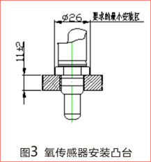
c. Installation requirements of
lug boss
Assembly materials of lug boss: stainless steel
The smallest outer diameter of lug boss:not less than
26 mm
The maximum thickness of lug boss: not more than 13
mm ( preferably between 9-13 mm)
The size of tapped hole:M18 × 1.5 – 7G
The quality of screw thread: the surface should be
no burr, trachoma, or any other defects that may affect
the installation and removal
The flatness of mounting surface is 0.2, the roughness
concentration of surface is Ra 3.2, the surface to the
heart of the vertical mounting holes is 0.2 degree
d. Assembly notes
The mounting torque of sensor: 40~60 Nm
Installation new sensor: The oxygen sensor has good
grease and smear with a protective cap before installed
thread department. Just remove the protection
cap before installation
Reinstallation sensor: Applying appropriate assembly
adhesive to smear the screw thread. Attentin: Do not
allow the protection of the contact assembly adhesives
Do not twist wiring harness when installation or screwing
in sensors. Do not pull the cable and plug
If the plug is dirty or damaged, do not use sensors
Using the cable tie to tie the long connecting cable
to circle
|


 c.
安装凸台要求:
c.
安装凸台要求: